1. Technical Proposal Description
1)The working environment of the machine
●Temperature: 0 ℃ -50 ℃.
●Humidity: Relative humidity below 35% -65%.
●Voltage: 440V 60Hz, 3 phase---customized
●Installation site: less dust
● Altitude: below 1000M
2, Main technical parameters of the machine
| No | Name | UNit | YD28-400T/200T |
| 1 | Nominal force | KN | 6000 |
| 2 | Maximum working pressure of liquid | MPa | 25 |
| 3 | Maximum tensile force | KN | 4000 |
| 4 | Maximum edge pressure | KN | 500*4 |
| 5 | Opening height | mm | 1200 |
| 6 | Stretch slider stroke | mm | 1000 |
| 7 | Effective area of workbench: Left and right column inner * front and rear edges | mm | 1300*1300 |
| 8 | Edge pressing slider stroke | MM | 900 |
3,Supply of main supporting parts:
| High pressure oil pump | Shaoyang Victor (http://www.shaoyecn.com) |
| Hydraulic system | Taifeng (http://www.taifenghydraulic.com) |
| Hydraulic cylinder | Factory |
| Motor | Huanqiu (www.js-hqdj.com) |
| an electric appliance | Schneider |
| PLC | Haiwell |
4, Safety protection:
| NO | Item | measure |
| 1 | mechanical protection | Electric motors and rotating components have rotation direction markings |
| There is a zebra crossing warning on the lower edge of the slider |
| 2 | Hydraulic protection | System overflow valve to prevent overpressure |
| 3 | Electrical protection | The electric motor adopts thermal relay protection |
| The control circuit protection adopts low-voltage circuit breakers |
| Emergency stop button |
| There is an overtravel switch protection at the bottom dead center of the slider |
| Safe and reliable grounding device |
| 4 | Operational safety measures | In case of emergency, press the "emergency stop" button |
| Safety sign: The bottom edge of the slider has zebra crossings, etc. |
5, Performance and characteristics:
This machine has an independent power mechanism and electrical system, and adopts PLC centralized control. The process action is manual and semi-automatic control mode. The hydraulic system adopts integrated plug-in valves, which are compact in structure, sensitive in action, and reliable. Fast speed, low energy consumption, and low noise. The working pressure and stroke range of this series of products can be adjusted according to work needs.
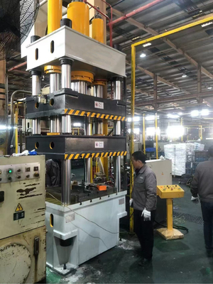
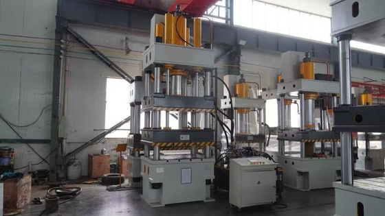
6, Structure Overview:
This machine consists of two main parts: the host and the control mechanism, which are connected by oil pipelines and electrical devices to form a whole. The main engine part includes the body, main cylinder device, etc. The control mechanism consists of hydraulic pump station, electrical box, mobile control console, etc. The structure and function of each part are described as follows::
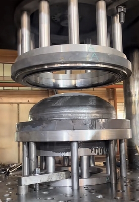
1)The body of this machine adopts a four beam and four column structure: it consists of upper crossbeam, deep drawing slider, edge pressing slider, worktable, main cylinder, lower top cylinder, column, control system, and electrical system..
2) Master cylinder: The master cylinder body is fixed to the table, and the lower end of the piston rod is connected to the slider with a flange, bolt, and slider. The piston head is divided into two oil chamber cylinders with YX sealing rings in opposite directions, and an O-ring is installed on the outer circumference of the guide sleeve, which is locked with flanges and bolts to ensure the sealing of the cylinder mouth. A dust ring is installed on the cylinder flange to ensure dust prevention of the piston rod..
3) Limiting device: The limiting device is installed on the right side of the machine and is mainly used to control the stroke distance of the slider. It consists of shims, contactless travel switches, etc..
4) Hydraulic station: The hydraulic pump consists of an oil tank, an axial piston pump, a motor, a two-way plug valve, a high-pressure self sealing oil filter, and an air filter, and is installed on the right side of the machine. The fuel tank is made of Q235 steel plate welded parts, and a pressure gauge is installed at the front end for the purpose of observing pressure. A level gauge is installed in the fuel tank to observe the oil level. A high-pressure self sealing oil filter is installed at the suction port of the oil pump to ensure the cleanliness of the pump and hydraulic system. An air filter is installed on the panel of the fuel tank, and when the upper cover is opened, refueling can be done..
5) Axial piston pump: This hydraulic system uses an axial piston pump. The instructions are provided in the user manual and will not be summarized here..
6) Two way plug-in valve: Its structure mainly consists of a plug-in component, a control cover plate, a pilot control valve, and an integrated valve block.
A plug-in component consists of a valve insert, a seal, a valve body, etc. It can be a cone valve or a slide valve structure. Its main function is to control the direction, pressure, flow rate, etc. of oil flow in the oil circuit.
B. The control cover plate is composed of various micro pilot control components and other hydraulic components embedded in the cover plate. The main function is to fix the plug-in components. Various embedded micro pilot control components combined with pilot control valves can control the working state of the plug-in valve. Control covers are divided into directional control covers, pressure control covers, and flow control covers.
C. The pilot control valve is installed on the control cover plate and is an electromagnetic directional valve that controls the action of the plug-in. Its component is an electromagnetic directional valve.
D. The integrated valve block is used to install plugins, control covers, and other control valves, and to communicate between the main oil circuit and the control oil circuit..
7, Overview of Hydraulic System
The hydraulic system consists of energy conversion devices (oil pump and oil cylinder) and energy transmission devices (oil tank, oil pipeline). With the help of electrical system control, the slider is driven to complete various action cycles.
8, Electrical control system
1. The machine is equipped with an independent electrical control box, which can be freely moved on both sides of the equipment, and the operation of the entire machine is controlled by centralized buttons.
9, Operating System
1. There are two operating modes: jog and semi-automatic, as well as two process operations: fixed range and fixed pressure.
2. The slider stroke is adjusted by a contactless switch control device.
3. The pressure of the master cylinder is adjusted by the pressure regulating valve.
4. The holding time can be freely set.

 Your message must be between 20-3,000 characters!