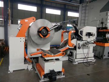
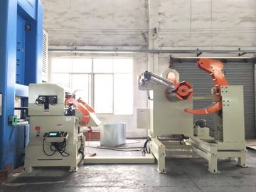
NCSF1300A medium sheet 3 in 1
Suitable width:70-1300
Suitable thickness :0.3-4.5mm
Model :NCSF6-1300A
overall performance of the equipment
Medium sheet 3 in 1 combines de-coiler, straighter and feeder, convenient to press material to straighter, small footprint, easy to operate, the lifting trolley can be selected and greatly facilitate material loading problems, is a perfect choice for stamping equipment.
The environmental conditions required by the equipment
1. environmental temperature: -10, -40
2. relative humidity: ≤ 90%
3. work power supply: AC380V + 10%, 50HZ, three-phase four wire system.
4. air pressure: 0.5MPa
5. feeding direction: from left to right (according to customer requirements)
Applicable material specification
- Material: cold rolled plate, pickling board, high power plate, galvanized sheet
- surface treatment: no
- Thickness: 0.3-4.5mm (refer to leveling capacity table)
- board width: 70-1300mm
- the yield point stress: ≤306N/mm
- the tensile strength: less than 490N/mm - (50Kgf/mm -)
- coil inner diameter: Φ 508mm(480-520mm)
- coil outer diameter: Φ 1500mm(800-1500mm)
- material weight: 10T
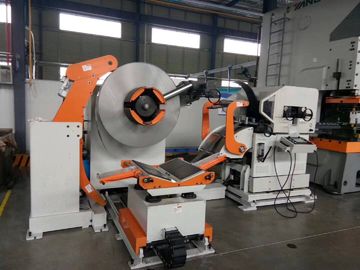
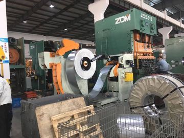
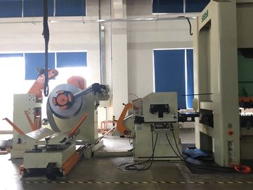
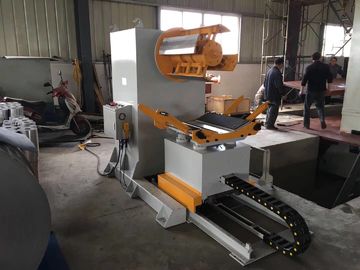
Equipment photos

Equipment overall size(L:4755mm,W:4459mm,H:2675m)


the overall structure features
1,Medium sheet 3 in 1, its straightener rollers are relaxes by piston cylinder in stead of air tank, suitable for material thickness 0.3mm ~ 4.5mm, width of 70mm ~ 1300mm roll feeding and straightening.
| Yield strength(N/mm²) |
245 |
306 |
| Tensile strength(N/mm²) |
392
40kgf/mm²
|
490
50kgf/mm²
|
| Plate thickness |
0.3 |
1300* |
1300* |
| 0.6 |
1300 |
1300* |
| 1.0 |
1000 |
950 |
| 2.3 |
480 |
410 |
| 2.5 |
330 |
290 |
| 3.2 |
200 |
150 |
| 4.0 |
160 |
115 |
| 4.5 |
110 |
93 |
1.3. Yield strength: MAX.306mpa
1.4. Material width: 70mm~1300mm
1.5, coil inner diameter: O 508mm (475~520mm)
1.6. Outer diameter of coil: O 800mm~ o 1500mm
1.7, material load: Max10T
1.8, feeding length: 0~9999 mm
1.9, feeding accuracy: + / - 0.15mm (longer than 500mm), greater than 500mm at + 0.2
1.10. Feeding speed: Max. 22m/min
1.11. Height of feeding line: normal feeding line height 1200 + 100mm (otherwise specified if user has special requirement).
1.12, oil pressure: 70 kg/mm2
1.13. Feeding direction: left to right.
1.14. Unwinding direction: lower unwinding mode.
2. Charging trolley
2.1 Function Description: When used in operation, the roll is smoothly transferred to the main shaft of the rack, and the trolley is provided with roll anti-dumping baffle plate, which can effectively prevent roll from tipping when transferring the material with small material range.
2.2. Material type: bearing surface is V face bearing form, surface padding wear resistant rubber pad treatment.
2.3, trolley load: 10T
2.4, trolley travel drive: hydraulic motor (throttle valve adjustment speed)
2.5. The lifting and driving of the trolley: hydraulic cylinder (keep the pressure valve running smoothly when the load is running).
2.6. The way of material coil alignment: hand-held operation handle visual alignment (with scale attached to equipment).
2.7, trolley walking to prevent offside: travel switch + hard limit block.
2.8, anti dumping baffle movement mode: manual adjustment
3. Discharge rack
3.1, Function Description: The discharging rack is to fix the discharging coil on the expanding and contracting part of the main shaft of the discharging rack, to support the support platform of the inner diameter of the discharging coil, and to start discharging intermittently through the control of the discharging ring in the automatic operation. It includes spindle expansion part, pressing arm part, stopping arm part, supporting arm part and material ring control part.
3.2. Width of material coil: 70mm ~ 1300mm
3.3. Load of material rack: 10T
3.4, expansion mode: Hydraulic wedge type.
3.5. Spindle expansion: 475mm- 520mm
3.6. Spindle drive motor: AC AC deceleration motor, inverter control
3.7. Active transmission mode: double row large pitch chain drive.
3.8. Spindle brake mode: pneumatic disc brake.
3.9. Spindle direction: counter clockwise (feed from left to right).
3.10, rack arm: compacting materials while preventing the loosening of the material coil after stripping, the speed of the roller will be automatically adjusted with the change of material coil diameter in the process of automatic operation, in order to achieve the linear speed matching between the roller and the coil, to prevent the material from rolling up.
3.11, pressure wheel specifications: PU rubber wheel 1.
3.12, the compression wheel drive mode: AC AC deceleration motor, inverter control.
3.13 Press wheel speed adjustment mode: by changing the angle of the press arm to change the analog signal input, so as to achieve speed change.
3.14, the movement of the press arm: pneumatic drive, can be manually up and down, automatic operation can choose to use or not to use.
3.15, baffle arm: located in the upper right of the rack, the surface of the baffle wheel is close to the side of the roll, the baffle wheel can rotate with any external force without power, which is used to prevent the belt from side slipping in the course of discharging.
3.16, width adjustment: manual adjustment.
3.17, block arm action: pneumatic drive outer gear up and down action, the inner gear does not move, only do the width of the scroll movement, the outer limit of the wheel action only touch screen manual operation, automatic operation must be in a downward position.
3.18. Gear wheel surface treatment: high frequency hard chromium plating.
3.19, support arm: lifting materials, easy to feed, using pneumatic drive, can rise and fall manually, in automatic operation, must be at the lowest point of the support arm.
3.20. Material ring control: when the material arc sags, the photoinductance switch under the support arm can bring feedback signal through the induction material, which can control the start and stop of the discharging rack, so as to ensure that there is enough reasonable buffer material arc between the discharging rack and the leveling feeder.
4. Leveling feeder
4.1 Function Description: Flatten the surface of the material, and according to the set length and speed of material feeding stamping equipment.
4.2, drive mode: AC servo motor, AC15KW
4.3. Leveling feeding roll combination: leveling roller, auxiliary wheel, feeding roller.
4.4. Leveling roll combination: 68mm * 7 leveling rolls (top 4 and bottom 3, surface thickening electroplated hard chromium grinding treatment, HRC 60 2)
4.5. Auxiliary wheels: 3 groups on top and bottom, 1 rows in each group (surface thickening, electroplating hard chrome grinding, HRC60 + 2).
4.6, feeding roller: 2 (surface thickening plating hard chromium treatment, HRC60 + 2)
4.7, leveling adjustment mode: manual adjustment.
4.8, leveling display mode: eccentric axis has a dial on it.
4.9, leveling setting accuracy: + 0.1mm (feeding distance exceeds 500mm, please explain).
4.10. Leveling roll support: deep groove ball bearings
4.11. Auxiliary wheel support: deep groove ball bearings
4.12. Release method of leveling roller: pneumatic type.
4.13. Leveling roller material: high carbon chromium bearing steel.
4.14, leveling accuracy: less than 1.0mm/ (200mm*200mm)
4.15, feed line height adjustment mode: electric adjustment, customer feeding line + 100mm
4.16. Roller drive mode: side gear drive, all gears are carburized and grinded by 6-level precision standard.
3.17. Repeat accuracy of feeding: + 0.2mm
3.18, maximum discharging speed: 22m/min
5. Discharge bracket device.
5.1 Function Description: Hard chrome plating roller is installed on the bracket to ensure the reliable transmission of the tape to the mold after the length is fixed. (bracket length standard 600mm, customers have special requirements, please explain in advance)
6, material head tail hydraulic scissors device
6.1, function description: hydraulic scissors are mainly used for shearing irregular materials.
6.2, applicable material width: 1300mm;
6.3, shear material thickness: 0.5-4.5mm. When the material is in the thickness range of 1.2mm-3.2mm, there is no need to adjust scissors gap.
6.4, scissors action mode: hydraulic drive;
6.5, scissors gap adjustment mode: manual adjustment, dial indicator display adjustment.
NCSF6-1300Aparameter
| No |
Item |
Value |
Unit |
Note |
| 1 |
Material width |
70~1300 |
mm |
|
| 2 |
Material thickness |
0.3~4.5 |
mm |
|
| 3 |
Material weight |
10000 |
kg |
|
| 4 |
Feeding speed |
22 |
m/min |
|
| 5 |
coil inner diameter |
Φ480-520 |
mm |
|
| 6 |
Coil outer diameter |
Φ800-1500 |
mm |
|
| 7 |
material enter roller |
2pcs,up 1/ down 1 |
pcs |
|
| 8 |
Straightening roller |
¢68×7pcs,up 4/ down 3 |
pcs |
|
| 9 |
Feeding roller |
2 pcs ,up 1/ down 1 |
pcs |
|
| 10 |
Feeding accurate |
From 0-500mm,±0.15mm/m |
|
|
| 11 |
Compressed air pressure |
0.55-0.7 |
Mpa |
|
| 12 |
decoiler expansion mode |
hydraulic |
|
|
| 13 |
Servo motor |
AC15 |
kw |
|
| 14 |
Decoiler motor |
AC5.5 |
kw |
|
| 15 |
Feeding direction |
L→R |
|
|
| 16 |
Feeding material line height |
customer ±100 |
mm |
|
| 17 |
material |
SPCC, Cold rolled plate, aluminium plate, pickled sheet |
|
|
| 18 |
Straightening correction |
Electric regulation |
|
|
IVIII,Standard configuration of major electrical components and power trains
| No |
Item |
Function |
Brand |
| 1 |
Photoelectric material arc control system |
Use description |
Omron |
| 2 |
Rack inverter |
Control rack operation |
Taiwan Delta |
| 3 |
Rack deceleration motor |
frequency control |
CPg |
| 4 |
Cylinder |
Rack operation |
CKD, Japan |
| 5 |
Pneumatic solenoid valve |
Driving effect |
CKD, Japan |
| 6 |
Leveling bearing |
Control cylinder |
NSK, Japan |
| 7 |
Servo driver |
Operation location |
Japan's Sichuan |
| 8 |
Servo motor |
Master control |
Japan's Sichuan |
| 9 |
Touch screen |
Main operation |
Taiwan fiber |
| 10 |
PLC |
Display and control |
MITSUBISHI, Japan |
| 11 |
Circuit breaker |
control |
Schneider |
| 12 |
Contactor |
Safeguard |
Schneider |
| 13 |
Control button |
Control main circuit |
Japan and the spring |
| 14 |
Relay |
Auxiliary function |
Japan and the spring |
| 15 |
Pneumatic components |
Auxiliary function |
Japan SMC/CKD |
| 16 |
Hydraulic components |
Drive function |
Taiwan brand |
Delivery: 60 days

 Your message must be between 20-3,000 characters!
 Please check your E-mail!
  Your message must be between 20-3,000 characters!
 Please check your E-mail!


